


Microgrids
Microgrid Solution
Designed for C&I parks, remote areas, and critical-load facilities, this solution integrates PV, energy storage, diesel generation, hydropower, and the grid into a multi-energy complementary microgrid system. Through unified dispatch by the EMS, multiple power sources operate in coordination, helping users improve supply reliability and reduce energy costs.
Core Values
Multi-Energy Complementary Stable Supply Source-Grid-Load-Storage Coordinated Optimization Full-Chain Visualized O&M
Pain Points
- ● Insufficient Supply Reliability: Users relying solely on the grid are prone to production interruptions during faults or power rationing, with direct losses at critical-load facilities.
- ● Volatile Energy Costs: Significant peak-valley tariff differences, with no storage regulation means, making it impossible to proactively avoid peak tariffs and keeping electricity expenditure high.
- ● Complex Multi-Source Management: Users with multiple power sources simultaneously lack unified dispatch means; each source operates independently, making coordination difficult and O&M inefficient.
Application
| Typical Scenario | Electricity Consumption Characteristics |
|---|---|
| C&I Parks | Concentrated loads, high daytime consumption, with PV conditions, sensitive to tariffs |
| Remote and Grid-Weak Areas | Unstable grid; requires local power sources such as diesel and hydropower to ensure supply |
| Critical-Load Facilities | Non-interruptible loads exist; requires multi-source redundancy to reduce outage risk |
Basic Requirements
1. Verifiable electricity bills and load data;
2. Suitable conditions for equipment installation, distribution connection, O&M, and communication.
PV capacity, storage configuration, and connection method shall be determined based on on-site assessment.
Solutions
Design Highlights
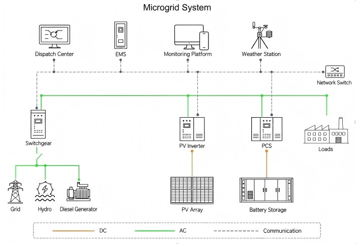
The system adopts an AC busbar architecture. PV connects to the AC busbar via the inverter, and storage via the PCS; the grid, hydropower, and diesel generators feed into the same busbar via switchgear, which then supplies loads. The EMS collects real-time data from each device and, in conjunction with weather information, coordinates multi-source output and storage charge/discharge.
- 1. Operating Strategy: When sunlight is sufficient, PV supply is prioritized, with surplus electricity stored in the battery; during peak-tariff periods, storage discharge is prioritized; when the grid is abnormal, the system may switch to local power supply according to preset strategies, with switching capability dependent on switchgear configuration and protection settings.
- 2. Configuration Confirmation: Based on load profile, PV output, site conditions, and reliability objectives, match power source combination, storage capacity, and PCS specifications, and verify communication compatibility and connection requirements.
System Connection Architecture
- 1. Generation Side: The grid, hydropower, and diesel generators connect to switchgear via AC cables, and after aggregation, connect to the AC busbar.
- 2. PV Side: The PV array outputs DC electricity, which is converted to AC by the inverter and connected to the busbar.
- 3. Storage Side: The battery connects to the PCS via DC cables; the PCS performs bidirectional AC-DC conversion, with the AC side connected to the busbar.
- 4. Load Side: The AC busbar supplies user loads via distribution circuits.
- 5. Communication Side: Each critical device connects to the communication network, interconnecting with the dispatch center, EMS, monitoring platform, and weather station to achieve data collection and command issuance.
System Components
The functions of each component are described below with reference to the topology diagram. Actual supply scope, product models, and features are subject to the project proposal.
| Component | Function |
|---|---|
| PV Array and Inverter | Converts solar energy into electricity and inverts to AC for connection to the busbar |
| Battery Storage and PCS | Stores electricity and charges/discharges according to strategy, achieving bidirectional AC-DC conversion and power regulation |
| Switchgear | Aggregates multiple AC power sources, performing switching, protection, and metering |
| Diesel Generator | Serves as backup or peak-shaving power source, starting when other sources are insufficient |
| Hydropower | Generates electricity using water power, serving as a local clean energy supplement |
| Utility Grid | Conventional supply source and backup power; coordinates with other sources when grid-connected |
| Energy Management System (EMS) | Core control unit; formulates and executes multi-source coordination and storage charge/discharge strategies |
| Dispatch Center and Monitoring Platform | Provides global dispatch, operating management interface, and real-time status display |
| Weather Station | Collects weather data such as irradiance and temperature, providing reference for PV forecasting and dispatch |
Values
Multi-Energy Complementarity Improves Supply Reliability
By integrating multiple power sources, the system no longer relies on a single supply path. The EMS automatically allocates output; when one source is constrained, other sources may take over supply according to preset strategies. Specific backup duration depends on storage capacity, diesel configuration, and switchgear settings, and must be assessed based on actual project conditions.
Source-Grid-Load-Storage Coordination Reduces Energy Costs
The EMS, in conjunction with tariffs, PV forecasts, and load profiles, coordinates storage charging during off-peak hours and discharging during peak hours, with PV prioritized for self-consumption, reducing peak-period grid purchases. Actual savings ratio is affected by factors such as tariff structure and load characteristics, and must be calculated based on specific data.
Full-Chain Visualization Improves O&M Efficiency
The dispatch center, monitoring platform, and EMS connect all critical devices through a unified network, centrally displaying operating status and alarm information. O&M personnel can grasp the overall situation without separately inspecting multiple systems, reducing manual operations and response delays.
Project Cases
Case 1 | California 2MW PV 4MWh ESS Hybrid Microgrid Project
Project Name and Location: California 2MW PV 4MWh ESS Hybrid Microgrid Project, California, USA
Commissioning Date: September 2022
System Scale: 2 MW PV; 2 MW / 4 MWh BESS; 6 MW fuel cell; multi-source complementary microgrid architecture
Project Overview and Results: Designed to cover 100% of the plant's energy demand, supporting continuous plant-wide power supply and off-grid operation. PV + fuel cell + ESS three-source coordination addresses round-the-clock production demand and solar irradiance fluctuations, enhancing outage resilience and reducing dependency on the regional grid.
Detail Link: View Details →
Get a Microgrid Solution Tailored to Your Enterprise
Provide the project location, recent electricity bills, load profile, and existing power source conditions to further assess microgrid configuration, connection method, and operating strategy.
Solutions
Contact Us
E-mail: info@onbipv.com
WeChat: +86 158 0002 4197
Whatsapp: +86 158 0002 4197


 WhatsApp
 Mail inquiry

