


Solar-Storage-EV Charging
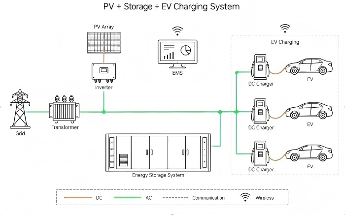
PV-Storage-Charging Solution
Designed for parking lots and fleet depots with PV construction conditions, this solution integrates a PV array, inverter, energy storage system, DC charging piles, and an EMS. The grid, PV, storage, and charging equipment are connected via an AC busbar. Subject to access and control conditions, the system coordinates PV generation, storage charge/discharge, and vehicle charging demand, mitigating the mismatch between generation and consumption periods and the power pressure from concentrated charging, and achieving synergy among generation, storage, and charging.
Core Values
Enhanced On-Site PV Utilization Mitigated Charging Peak Pressure Coordinated Energy Management
Pain Points
- ● Mismatch Between Generation and Charging Times: PV output is affected by sunlight, and vehicle arrival times vary; generation and charging peaks may be offset, making it difficult to fully utilize on-site green electricity.
- ● High Concentrated Charging Power: Simultaneous fast charging of multiple vehicles pushes up the depot's instantaneous load; existing distribution capacity may limit charging equipment usage, affecting peak-hour service.
- ● Difficult Coordinated Energy Dispatch: Operating status of generation, storage, and charging equipment is siloed; managers struggle to coordinate energy supply-demand and charging arrangements, increasing daily coordination effort.
Application
| Typical Scenario | Electricity Consumption Characteristics |
|---|---|
| Public Parking Lots with PV Carports | Charging demand varies with passenger flow; requires coordination between PV output and load |
| Logistics and Commuter Fleet Charging Depots | Vehicles return in concentrated batches; requirements for available power and charging completion time |
| Parking Areas Attached to Commercial Facilities | Charging demand fluctuates with operating hours; load arrangement must consider distribution margin |
Basic Requirements
1. Provide consumption curves, tariff data, vehicle arrival/departure patterns, and charging demand to clarify construction objectives.
2. Available installation space for PV, storage, and charging equipment, with verified structural load, fire safety, maintenance access, and electrical connection conditions.
3. Equipment communication, network access, and daily O&M conditions, with confirmed compatibility of on-site equipment interfaces.
Capacity, configuration, and connection method shall be determined based on on-site assessment.
Solutions
Design Highlights
The topology adopts an AC busbar aggregation architecture: the PV array outputs AC via the inverter, the storage system connects to the same busbar, the grid connects to the busbar via a transformer, and DC charging piles draw power from the AC side and output DC to vehicles. The EMS is used for energy monitoring and coordination; data collection and control execution are subject to interfaces and configuration.
- 1. Operating Strategy: May be designed around the principle of prioritizing on-site PV utilization; when generation is surplus and storage permits, it charges; when charging load is high, storage assists in supplying power, with the shortfall supplemented by the grid. Specific strategies are constrained by connection power, storage state of charge, vehicle demand, and grid connection conditions; surplus electricity handling is to be confirmed separately.
- 2. Configuration Confirmation: Based on sunlight, area, hourly load, and refueling windows, match PV power, storage power and capacity, and charging pile quantity and power; verify transformer margin, wiring, protection, and metering configuration.
System Connection Architecture
- 1. Generation Side: The PV array connects to the inverter via DC lines, then to the busbar via AC lines, completing power conversion.
- 2. Storage Side: The storage system connects to the busbar via AC lines, storing and releasing electricity; internal battery and conversion equipment configuration is not detailed.
- 3. Grid Side: The grid connects to the busbar via a transformer through AC lines, providing grid-side access. Reverse power feed conditions must be verified.
- 4. Charging Side: DC charging piles are connected in parallel to the AC busbar, then to vehicles via DC lines; quantity is subject to project design.
- 5. Communication Side: The EMS and charging area are equipped with wireless communication; equipment docking scope, communication method, and control authority must be confirmed in the design.
System Components
The functions of each component are described below with reference to the topology diagram. Actual supply scope, product models, and features are subject to the project proposal.
| Component | Function |
|---|---|
| PV Array | Converts solar energy into DC electricity, providing PV power for the depot |
| PV Inverter | Converts PV DC to AC and connects to the busbar |
| Energy Storage System | Exchanges electricity with the system via the AC side, charging and discharging under permitted operating conditions; internal configuration to be confirmed |
| EMS (Energy Management System) | Used for energy monitoring and coordination management; monitoring scope and dispatch capability depend on actual interfaces and configuration |
| DC Charging Pile | Draws power from the AC busbar, converts it to DC required by vehicles, and completes the charging connection |
| Grid and Transformer | Used for grid connection and voltage transformation; not included in supply by default |
| Electric Vehicle | Serves as the service target; interface and acceptable power affect refueling arrangements |
Values
Improved Flexibility in PV Utilization
Through coordination between PV supply and storage time-shifting, surplus PV electricity is used for subsequent charging, improving the mismatch between generation and consumption times; actual utilization level depends on output, load, and storage configuration.
Mitigated Charging Peak Pressure
When storage state of charge and output power permit, provides partial power support for concentrated charging, relieving peak pressure at the grid connection point and improving peak-period service capacity.
Improved Operating Management Efficiency
After equipment docking, the EMS aggregates operating information within the agreed scope, supporting charging arrangement and storage strategy adjustment, reducing scattered viewing and manual coordination.
Project Cases
Case 1 | Tianjin Urban Distributed Microgrid Demonstration
Case Name: Tianjin Urban Distributed Microgrid Demonstration
Date: October 2025
Scale: 20.65 kWp PV carport, 145 kW / 261 kWh integrated liquid-cooled ESS, 1×240 kW ultra-fast DC charging pile (1×600A liquid-cooled terminal + 2×120 kW dual-gun terminals), 2×7 kW AC slow-charging terminals, EMS
Detail Link: View Details →
Get a PV-Storage-Charging Solution Tailored to Your Depot
Please provide the project location, available rooftop or carport area, transformer capacity, consumption curve, tariffs, and vehicle charging demand, so that we can assess configuration and implementation conditions.
Solutions
Contact Us
E-mail: info@onbipv.com
WeChat: +86 158 0002 4197
Whatsapp: +86 158 0002 4197


 WhatsApp
 Mail inquiry

