


Commercial and Industrial
Commercial & Industrial Energy Storage System Solution
Designed for centralized electricity consumption scenarios such as manufacturing enterprises and industrial parks, this solution configures energy storage in coordination with PV, distribution facilities, and an EMS, focusing on energy management functions such as peak shaving and valley filling and PV consumption, to help enterprises optimize electricity costs.
Core Values
Reduced Electricity Costs Optimized Consumption Peaks Enhanced Energy Management Capability
Pain Points
- ● High Peak-Hour Electricity Costs: Production and operating loads are concentrated during high-tariff periods, and enterprises lack flexible regulation means, making it difficult to fully utilize electricity from low-tariff periods.
- ● Load Peaks Create Capacity Pressure: Concentrated equipment startup or phased production increases push up consumption peaks, increasing the difficulty of distribution capacity management and potentially creating demand for capacity expansion.
- ● Mismatch Between PV Generation and Consumption Times: Enterprises with PV conditions may have insufficient consumption during generation peaks, while still requiring significant grid purchases during evenings or production peaks.
- ● Scattered Operating Information: PV, storage, and meter data are siloed, making it difficult to grasp overall energy status in a timely manner; critical loads also require backup power planning in conjunction with business continuity requirements.
Applicable Scenarios
| Typical Scenario | Electricity Consumption Characteristics |
|---|---|
| Manufacturing Enterprises | Large electricity consumption, clear shift patterns, with peak-valley tariff spreads or short-duration load peaks |
| Industrial Parks | Concentrated diverse loads, suitable for energy coordination in conjunction with unified metering and management conditions |
| Commercial and Transportation Support Facilities | Operating, air-conditioning, or charging loads vary by time period, with load regulation needs |
Basic Requirements
1. Verifiable electricity bills and load data.
2. Suitable conditions for equipment installation, distribution connection, O&M, and communication.
PV capacity, storage configuration, and connection method shall be determined based on on-site assessment.
Solution Approach
Design Principles
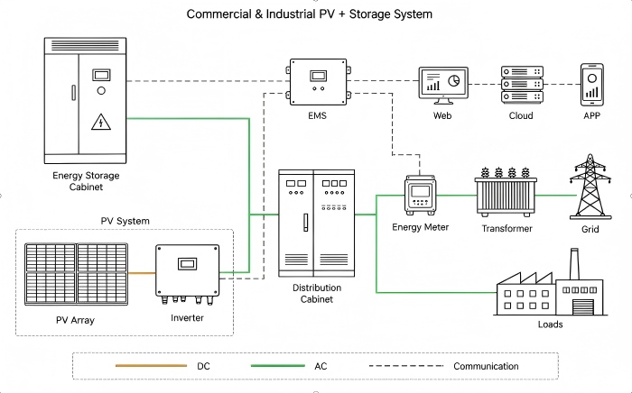
The system adopts an AC-side coordinated architecture. The PV array connects to the distribution system via the inverter, and the storage cabinet operates in coordination with PV on the AC side; enterprise loads draw power through the distribution system; the grid connects via a transformer and metering stage. The EMS collects storage, PV inverter, and meter data, and coordinates equipment operation according to set strategies.
- 1. Charge/Discharge Strategy: Charging is scheduled during low-tariff periods or periods of PV surplus, and discharging during high-tariff periods or load peaks; the strategy is then adjusted in conjunction with load changes, storage state of charge, and equipment operating boundaries.
- 2. Configuration Confirmation: Based on load profile, peak duration, PV output, and site conditions, match storage power and capacity, and verify communication compatibility, metering location, and connection requirements.
System Connection Architecture
- 1. PV Side: The PV array outputs DC electricity, which is converted to AC by the PV inverter and connected to the distribution system.
- 2. Energy Storage Side: The storage cabinet connects to the AC distribution system, absorbing or releasing electricity according to operational strategies, and jointly supplies enterprise loads together with PV and the grid.
- 3. Grid and Load Side: The grid connects to the enterprise distribution system via a transformer and metering stage; production, operating, and supporting loads are supplied by the distribution system.
- 4. Communication Side: The EMS connects to the storage cabinet, PV inverter, and electricity meters, providing operating management access via web portal, cloud platform, and mobile app.
System Components
The functions of each component are described below with reference to the topology diagram. Actual supply scope, product models, and features are subject to the project proposal.
| Component | Function |
|---|---|
| Storage Cabinet | Stores electricity and charges/discharges according to strategy; integration method of battery, bidirectional converter, and supporting management and safety systems is determined by product configuration |
| PV Array and Inverter | Converts solar energy into electricity and converts DC to AC for connection to the distribution system; applicable to projects with PV conditions |
| Distribution Cabinet | Aggregates and distributes AC electricity, performing corresponding connection, switching, and electrical protection functions |
| Energy Management System (EMS) | Collects operating data and executes coordinated control in conjunction with tariff periods, load, and storage status |
| Electricity Meter | Provides metering data such as power and electricity, providing the basis for operating monitoring and strategy adjustment |
| Transformer and Grid Connection | Connects the enterprise distribution system to the grid; capacity and connection method must be verified against on-site conditions |
| Web Portal / Cloud Platform / Mobile App | Provides operating data display and remote management access; actual features depend on platform configuration |
| Enterprise Load | Production, operating, and supporting electrical equipment served by the system; critical loads must be identified separately according to assurance objectives |
Solution Value
Reduced Electricity Costs
By charging during low-tariff periods and discharging during high-tariff periods, the timing of grid purchases is optimized; in conjunction with PV generation utilization, enterprises' ability to regulate electricity costs is improved (savings must be calculated comprehensively based on actual expenses).
Mitigated Peak Load Pressure
Storage supplements supply during consumption peaks, reducing grid draw peaks in certain periods. When power, duration, and connection conditions meet requirements, capacity pressure can be alleviated.
Improved Management Efficiency and Supply Resilience
Centralized viewing of PV, storage, and consumption data supports operating analysis and strategy optimization.
Project Cases
Case 1 | Guangdong 20–150kW Photovoltaic Power Station Project
Project Name & Location: Guangdong 20–150kW Photovoltaic Power Station Project, Guangdong, China
Commissioning Date: 2025
System Scale: 20–150kW Grid-Tied PV Inverter; Annual Power Generation Approx. 11 Million kWh; Annual CO₂ Reduction 10,967 Tons
Detail Link: View Details →
Get a Storage Solution Tailored to Your Enterprise
Provide the project location, recent electricity bills, load profile, and existing PV conditions to further assess storage configuration, connection method, and operating strategy.
Solutions
Contact Us
E-mail: info@onbipv.com
WeChat: +86 158 0002 4197
Whatsapp: +86 158 0002 4197


 WhatsApp
 Mail inquiry

